XV-15 Tiltrotor CFD Case Study
Despite a projected 40.3 million flights worldwide in 2020, airplanes actually have a major drawback. To take off, airplanes need to accelerate along a runway to reach the necessary speed to generate lift and become airborne. This limitation sparked the development of helicopters which use rotating rotor blades, instead of fixed-wings, to generate lift. This allows helicopters to take off and land vertically, removing the need for long runways.
However, helicopters come with their own restrictions which includes shorter ranges and slower speeds. Consequently, a new type of aircraft, the tiltrotor, was developed which combined the hover and vertical take-off and landing (VTOL) capabilities of helicopters with the speed and range of airplanes.
As the name suggests, tiltrotors utilise tilting rotor blades that are mounted to shafts at the end of fixed wings. During vertical flight, the plane of rotation of the rotors is horizontal, generating lift in a similar way to a helicopter. As the aircraft’s speed increases, the rotors progressively tilt forwards until the plane of rotation is vertical at cruising speeds. Here, the rotors act as propellors, providing thrust, while the fixed wings generate lift, just like an airplane.
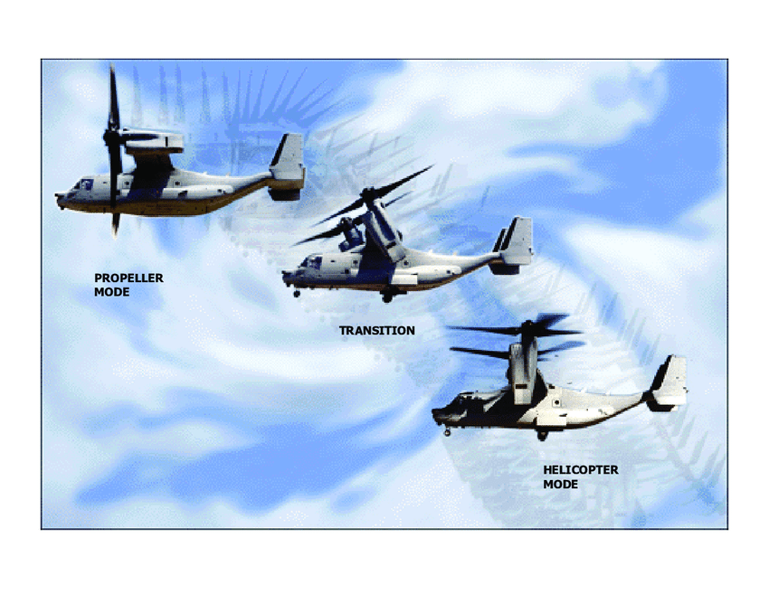
The result is an aircraft which can switch between helicopter mode and airplane mode during flight, whilst achieving higher altitudes and greater speeds then a helicopter. These capabilities have attracted a huge amount of investment in the past and in the late 1960s, NASA together with Bell Helicopters developed the Bell XV-15 which has become the foundation for many VTOL aircrafts today.
Tiltrotor in CFD
To operate efficiently in both helicopter and airplane modes, the XV-15’s rotor blades feature complex geometry with high twist and solidity as well as a small rotor radius. This, along with the wide range of operating conditions makes it extremely difficult to accurately model tiltrotor rotor blades in CFD.
A few studies have been completed in the past which analysed the hover and airplane modes of the XV-15. These were based on full domain numerical simulations of the Navier Stokes equations. However, there has never been a comprehensive numerical study on the hover and propulsive/descending forward flight helicopter mode and airplane mode of a full-scale XV-15. To test the accuracy and performance of its Flow360 solver, Flexcompute decided to conduct such a study.
Model geometry
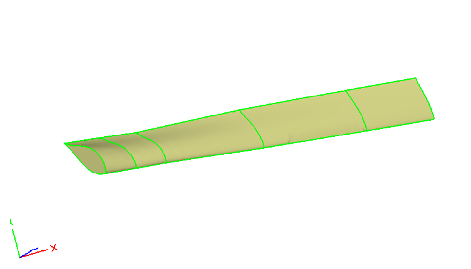
The XV-15 rotor is made up of three individual rotor blades, each consisting of five NACA 6-series aerofoil sections. The geometric properties of the full-scale XV-15 rotor were used to create the geometry file using the Engineering Sketch Pad.
Meshing
To accurately capture the behaviour of the airflows both around the aircraft and around the blades, a multiblock unstructured meshing approach was adopted. The entire domain was split into two blocks: 1) Farfield block acting as the stationary domain 2) Nearfield block acting as the rotational domain, containing the three rotor blades.
The farfield block (yellow) was designed large enough to ensure an independent solution with the boundary conditions employed. The nearfield block was merged by four components: a cylindrical off-body mesh and three cylindrical body-fitted meshes (orange) containing the blades (green). This allowed for CFD simulations to be completed over a range of blade collective angles from 0 to 18 degrees by regenerating the cylindrical body-fitted meshes perspectively.
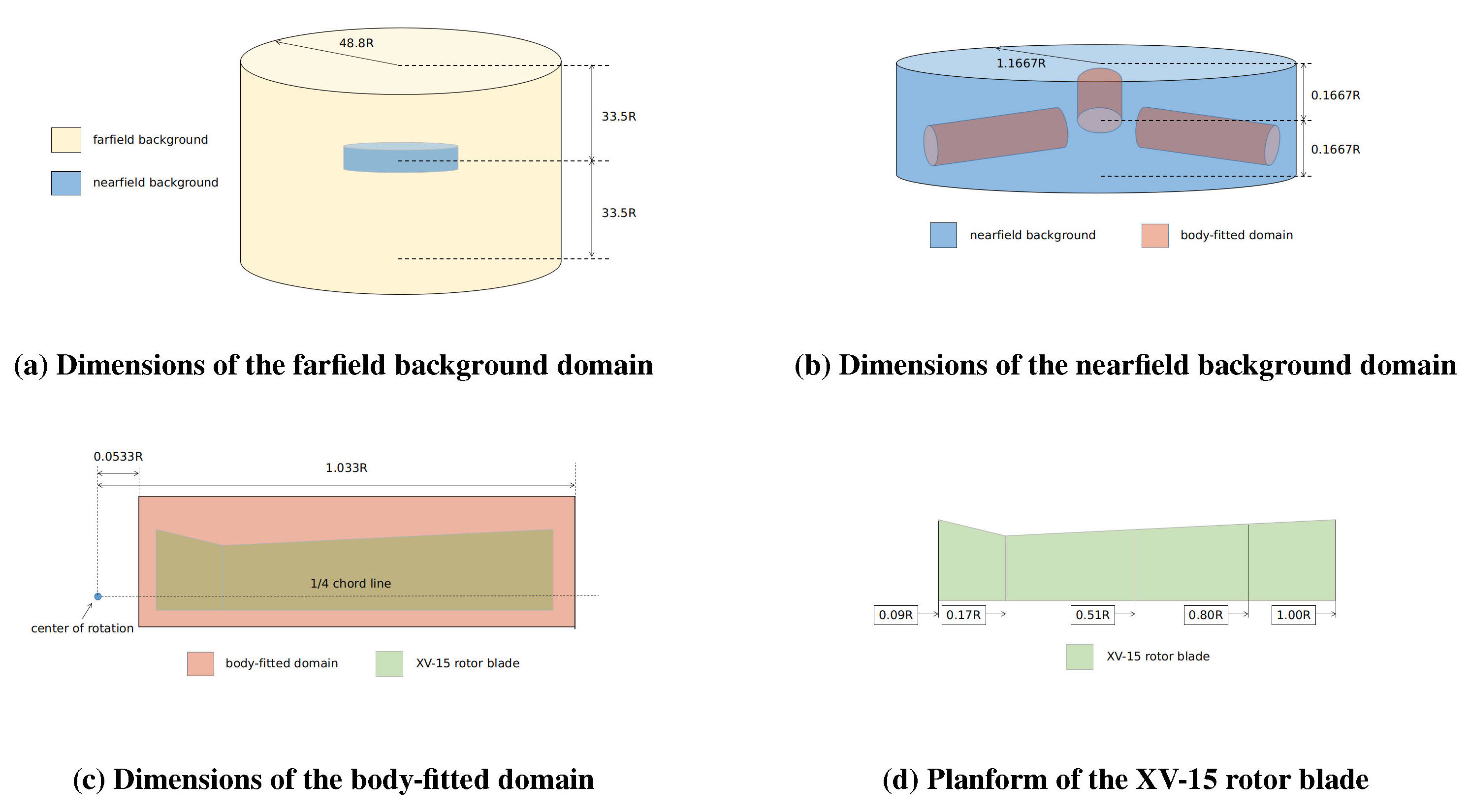
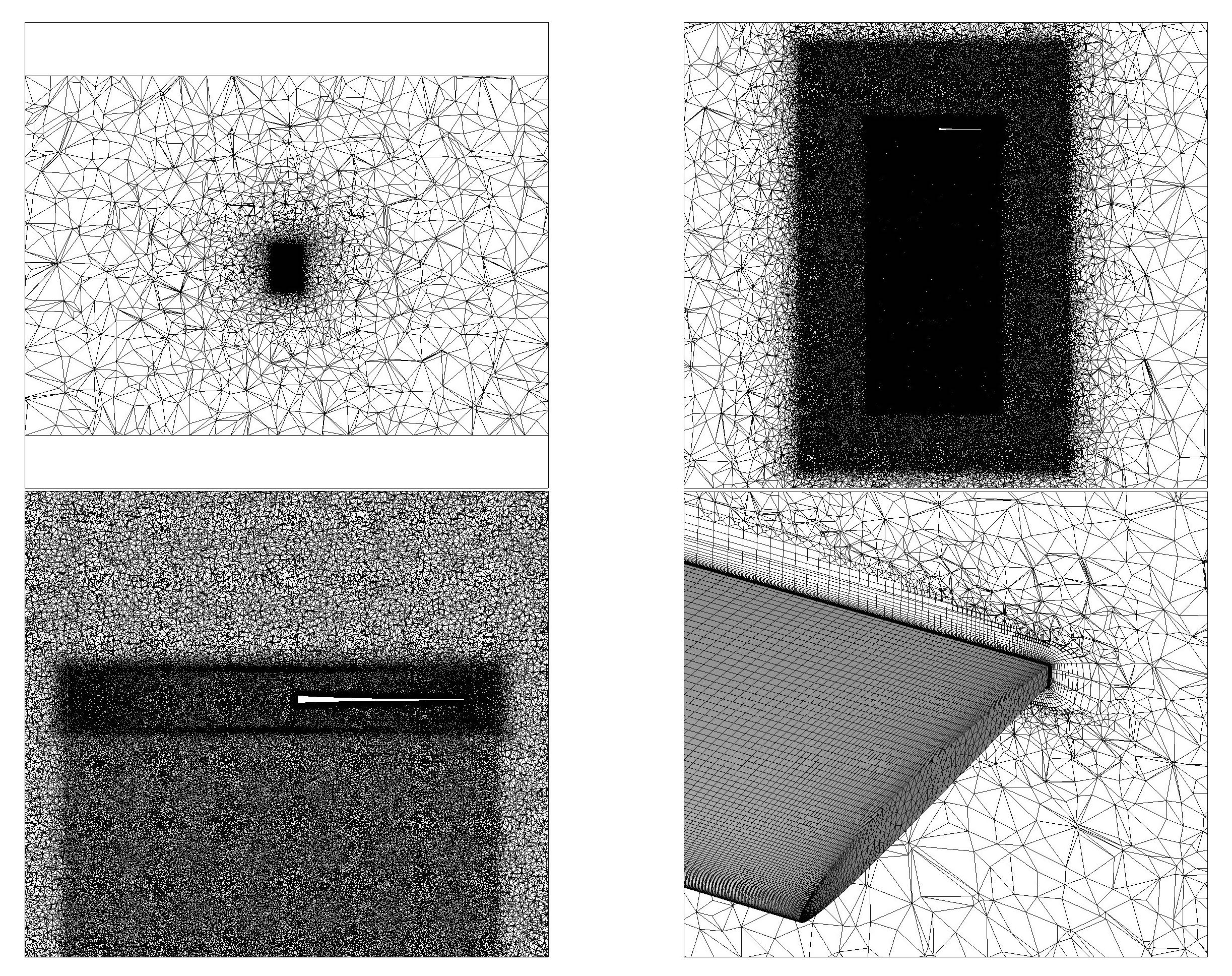
The meshing process started with creating a cylindrical body-fitted mesh, which was then rotated along the axial direction to generate the other two body-fitted meshes. These were merged with the off-body mesh, with any overlapped nodes combined into a single node, resulting in one conforming mesh for the nearfield block.
The overall mesh consisted of a mixture of hexahedral, tetrahedron, prismatic and pyramidal cells to achieve the optimum balance between resolution and computational time. The mesh was further refined in particularly complex areas such as the viscous boundary layer near the blades which involved over 40 layers of hexahedral cells.
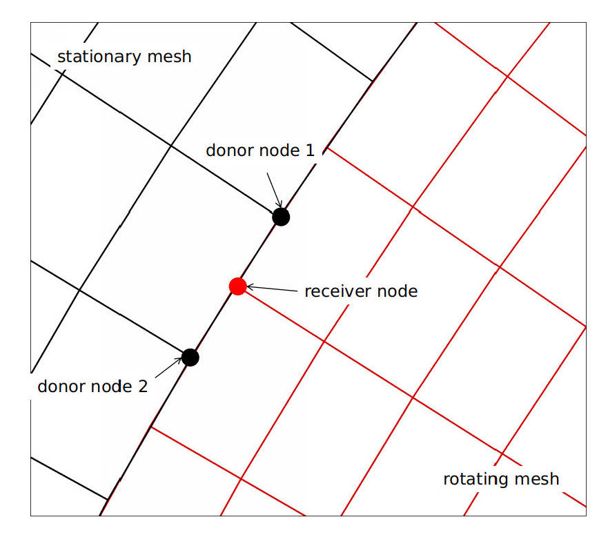
To model the rotating blades, the nearfield block will rotate within the stationary farfield block and so a sliding mesh interface needs to be solved. At each timestep, receiver nodes on the rotating mesh detect the two closest donor nodes on the stationary mesh. The receiver’s node’s solution is then linearly interpolated from the solutions of the two donor nodes and the process repeats for the next timestep.
CFD Results
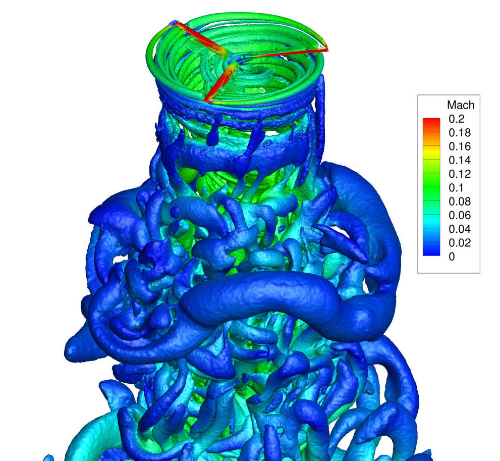
The CFD simulations for this study used the Detached Eddy Simulations (DES) method together with Spalart Allmaras (SA) turbulence models. A range of results were analysed including overall and sectional blade loads, surface pressure coefficient, skin friction and the flowfield details. To validate the accuracy of the Flow360 solver, these results were compared with either previous CFD studies or experimental data from full-scale NASA wind tunnel tests where available.
Overall blade loads
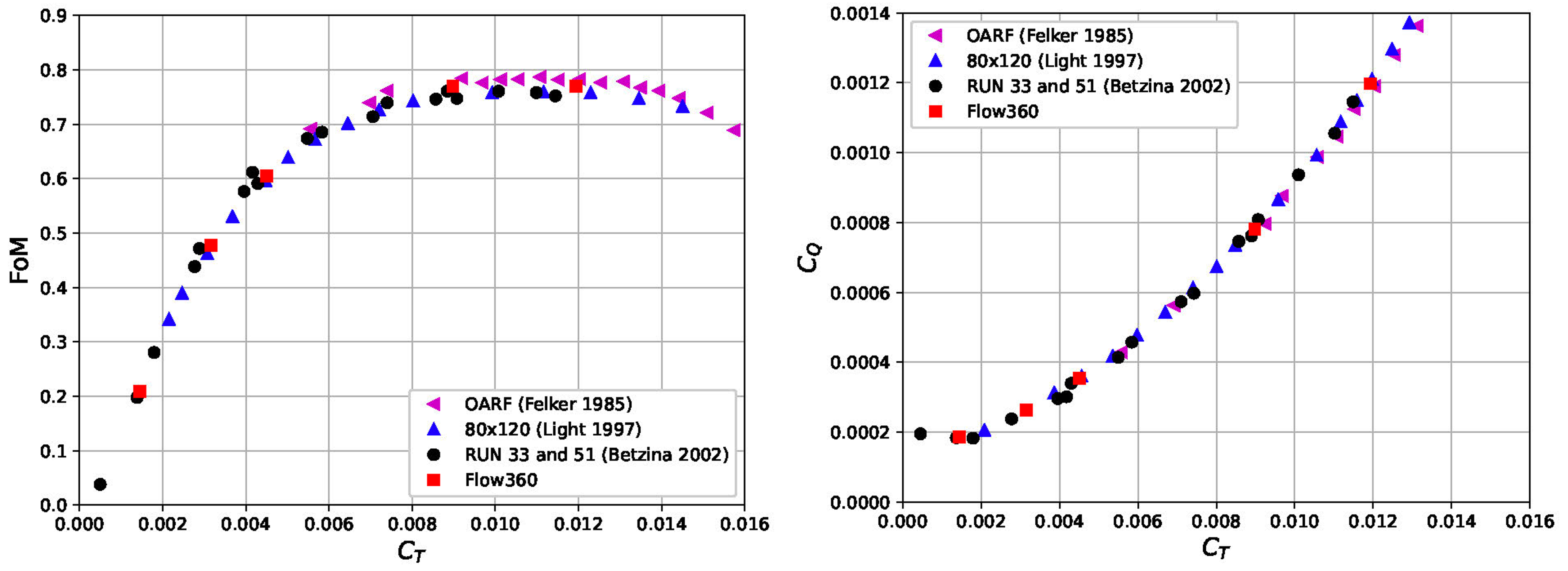
The figure of merit (FoM) and torque coefficient (CQ) as functions of the thrust coefficient (CT) for hovering flight of helicopter mode were compared with three sets of experimental data. In both cases, the Flow360 results showed a strong correlation with wind tunnel measurements.
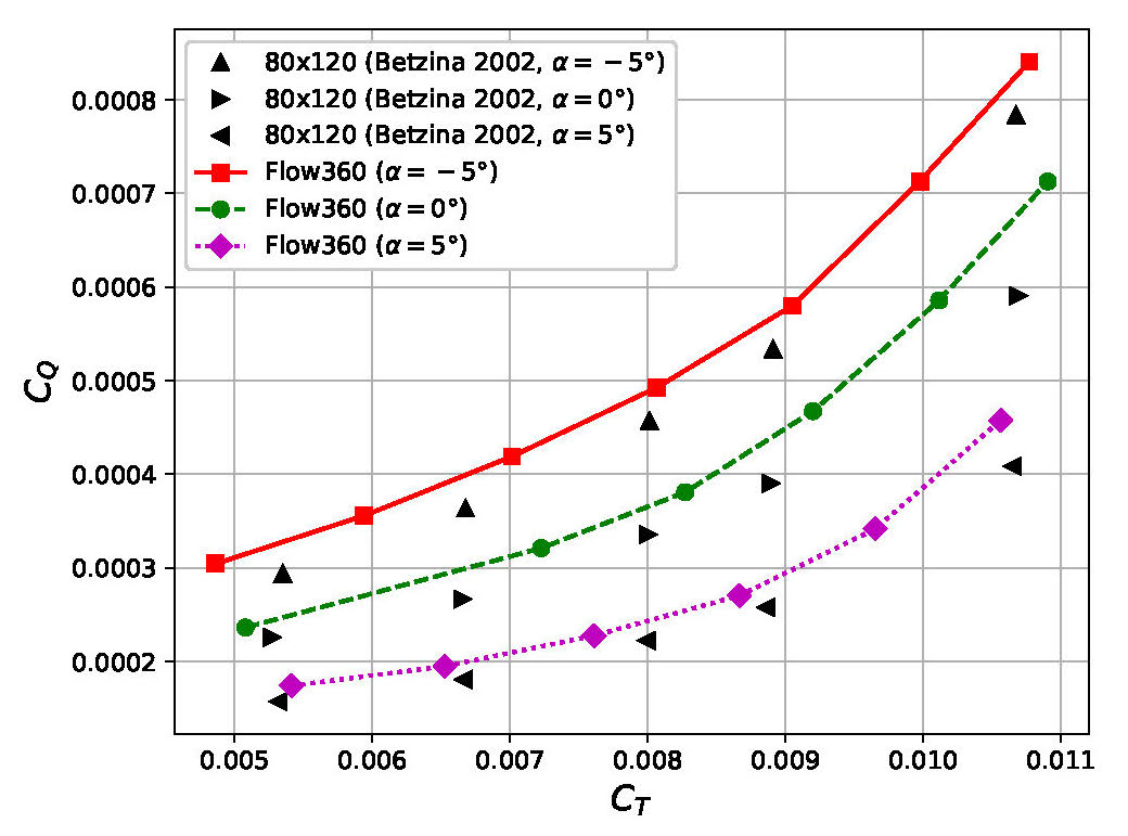
To analyse CQ and CT for forward flight helicopter mode, the shaft angle was varied to replicate a range of both propulsive and descending forward flight conditions. Compared to experimental data, the predicted rotor performance shows similar trends, but has a 4-14% relative error. Due to the lack of more precise pressure distribution and skin friction experimental data to validate these CFD results further, a grid resolution and time integration study will be completed in future to identify the reasons for these discrepancies.
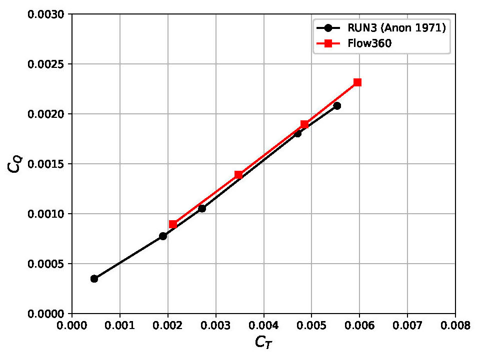
For airplane mode, simulations were performed across a range of collective pitch angles and the results show good correlation with data from a previous CFD study and experimental data where available.
Pressure distribution results
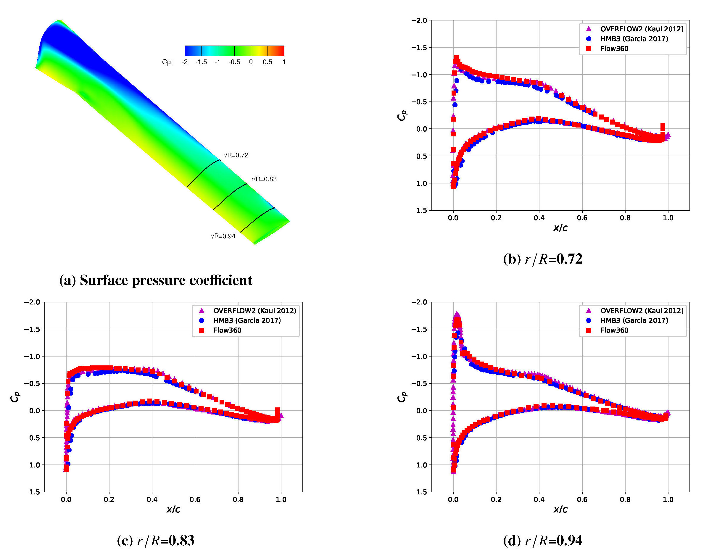
To validate the predictive capabilities of Flow360 in capturing more detailed physics, the surface pressure distribution of the blades in hovering flight were also investigated. With no experimental data available, previous CFD studies using OVERFLOW2 and HMB3 codes were used for comparison.
Three radial stations were selected for the collective pitch angle of 10 degrees and the surface pressure coefficient (CP) was calculated based on the local rotating velocity at each radial station. In all three cases, the results from Flow360 align closely with the OVERFLOW2 and HMB3 results.
Overall, a detailed CFD study on the hovering and forward flight helicopter mode and airplane mode was conducted using Flow360 software from Flexcompute. After a thorough analysis and comparison with experimental data and previous CFD studies, Flow360 was proven to accurately predict the performance of the rotor blades in both hovering flight of helicopter mode and airplane mode. Further investigations will be conducted to fully validate Flow360’s potential to predict more detailed phenomena in forward flight helicopter mode.
For a deeper dive please refer to “Assessment of Detached Eddy Simulation and Sliding Mesh Interface in Predicting Tiltrotor Performance in Helicopter and Airplane Modes” in Flow360 Publications

