CFD Simulation Methods for High-Lift Aircraft Configurations (Part 1 of 3)
In this series we will highlight contributions to the 4th AIAA High Lift Prediction Workshop using a variety of CFD simulation techniques. The full series consists of three parts: Part I provides essential background motivation for carrying out this study. Part II will detail our modeling strategy and discuss the computational fluid dynamics approach. Part III will showcase the results and how they are useful in enhancing our understanding of flow behavior in high-lift configurations.
PART I – 4th AIAA High Lift Prediction Workshop
Wing Design
Airplanes come in all shapes and sizes, from tiny single seaters to gigantic ones like the Airbus A380 measuring up to 70 meters in length; they also fly at very different speeds. The many design elements are primarily driven by the operating conditions (e.g., maximum and minimum operating speeds and maximum load capacity) under which the aircraft will be flown.
It is not an exaggeration to say that a fixed-wing airplane is essentially a payload-carrying structure attached to its wings. The wings are a fundamental design element of an airplane and largely dictate which conditions the airplane can be operated at. As such, substantial effort is dedicated to the design of wings because of their critical importance to airplane performance.
Most importantly, the wings of an airplane provide lift which allows it to go airborne and fly. The lifting capabilities of a wing design depend on the angle at which incoming air flow “attacks” the wing (called angle-of-attack or simply ⍺) and the velocity at which it flows.
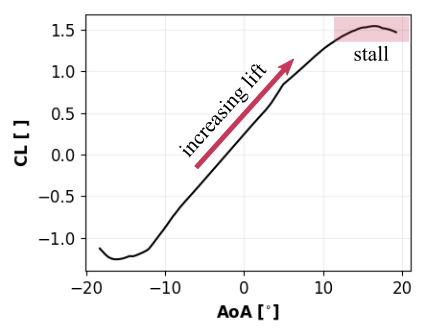
For a given “freestream” flow velocity, defined at a far away distance from the wing, the lifting capability of a wing – generally measured in terms of a lift coefficient CL – increases as ⍺ increases. However, this happens until ⍺ reaches a critical value, after which CL rapidly drops. For ⍺ larger than this critical value, the aircraft is said to be in a “stall” condition (see Figure 1). In such conditions, the aircraft rapidly loses lift and can become unstable, which is clearly a major safety hazard. For a much more detailed discussion of aerodynamic stall, please refer to our earlier article on this issue.

Figure 1: Coefficient of lift (CL) vs angle-of-attack (AoA) for a NACA 2412 airfoil.
For anyone designing a fixed-wing aircraft, knowing how the CL of a potential wing design will behave at different ⍺, and, more crucially, when the wing might go into a stall regime, is a critical piece of information.
Experimental prototyping of every possible design iteration of a wing in a wind tunnel or elsewhere would be extremely laborious and carries a large financial cost. In these cases, we use the power of modern computers to simulate the relevant physics involved and narrow down to a few promising candidate designs which may then be tested experimentally. Therefore, the field of computational fluid dynamics (CFD) plays a fundamentally important role in modern aircraft design.
The High Lift Prediction Workshops
Despite the major progress that has been made in CFD, we have not reached a stage where CFD can faithfully mimic the physics involved in all scenarios and all wing configurations. It is typical to employ context and condition dependent CFD models and approximations that work in some parameter regimes but fail in others.
In order to make measurable progress in this complex problem of predicting and modeling the lift of an aircraft wing, especially at the high-lift configurations which are needed during takeoff and landing, NASA and AIAA organize the High Lift Prediction Workshops (HLPW). The underlying goal is to assess the limits of CFD modeling techniques and approximations in order to develop best-practices and understand the flow physics critical to high-lift predictions. These limits are imposed by things like numerical errors, physical modeling errors, and resource constraints. Accurate CFD predictions will lead to reduced future program development costs and risks, as well as enable high-lift aerodynamic optimization, which is crucial for the development of new aircraft designs with superior performance.
During the 1st workshop of the series, the Trapezoidal Wing was investigated, with a major focus on predicting flap/slat support effects. The 2nd workshop focused on the DLR F11 passenger airplane model, with test cases examining the sensitivity to Reynolds number effects, transition, and slat geometric details. The 3rd workshop investigated the High Lift Common Research Model (HL-CRM) geometry as well as nacelle installation effects for the JAXA JSM model. During the first three editions of the HLPW, the majority of simulations were based on using the Reynolds-Averaged Navier-Stokes (RANS) equations with limited submissions involving fluid flow scale-resolving simulations, mainly due to the associated high computational costs of such models.
In this series of articles we will discuss Flexcompute’s contribution to the 4th AIAA High Lift Prediction Workshop (HLPW-4) and discuss the results obtained with Flow360. In particular, we will focus on establishing best-practices for high-lift RANS predictions near max CL. We will also detail comparisons of the best-practice RANS results with respect to scale-resolving Detached Eddy Simulations (DES).
This concludes PART I of the series. In PART II, we will discuss some of the key details of our CFD modeling strategy and how Flow360 is used to carry out such simulations.
Before you leave, you may also be interested in checking out an article on the results obtained for HLPW-3 where Flow360 showed a speedup of 73x compared to other CFD solvers!
If you’d like to learn more about CFD simulations, how to optimize them, or how to reduce your simulation time from weeks or days to hours or minutes, stop by our website at Flexcompute.com or follow us on LinkedIn.
For the expanded version of the paper this content is derived from, see An Analysis of Modeling Sensitivity Effects for High Lift Predictions using the Flow360 CFD Solver.


