Tiltrotor Propulsion Modeling with Blade Element Theory (Part 2 of 3)
In this series, we highlight our continued effort to study the fluid dynamics of the XV-15 tiltrotor aircraft. The full series consists of three parts: Part I provides some background on the need and utility of tiltrotor aircraft and summarizes the CFD study we carried out in 2021 using the Detached Eddy Simulation (DES) technique. Part II will discuss useful fluid dynamic propulsion approximations to model the XV-15 at a reduced computational cost. Part III will showcase the results obtained using the propulsion approximations.
##
In the first part of this series, we discussed the utility of the Detached Eddy Simulation technique to model an XV-15 tiltrotor and similar aircraft. We found a very good agreement between the results obtained using our Flow360 solver and the available experimental results and earlier simulation studies. In this part, we discuss in detail a few propulsion approximations which can be used to dramatically cut the computational cost of simulating an aircraft involving a rotor system, compared with a simulation employing a body-fitted rotating grid on the blades.
Modeling the movement of fluid around propellers can be a difficult task for computers. The high rotation speeds and narrow blades of propellers can create very fast and complex interactions among the fluid flows associated with each blade. However, many scientific and engineering problems can be simplified with mathematical models. This allows us to understand the important physics of the problem while using fewer computational resources, making industrial studies more efficient.
Over the years, researchers have shown that the complex fluid dynamics of propellers can be approximated by simpler models. Let us discuss two appropriate models: the transient Blade Element Theory (BET Line) and the steady Blade Element Theory (BET Disk). These models make assumptions about the physics of the problem to simplify the calculations.
Propulsion approximations
The Blade Element Theory (BET) model is a significant improvement over the Actuator Disk (AD) model. Let us first discuss the AD model to lay down some basic ideas.
The Actuator Disk (AD) model is a simplified method used to model the fluid dynamics of rotor propulsion systems such as wind turbines or helicopter rotors. In this model, the individual blades of the rotor are ignored, and the entire rotor is modeled as an effective disk. The disk is assumed to take in fluid from the upstream side, perform mechanical work, and push out the accelerated fluid from the downstream end.
This simplification allows for the calculation of the rotor’s influence on the flowfield using only two parameters: the axial force, or “thrust”, directed along the upstream-to-downstream sides of the propeller-motor system and the circumferential force, or “torque”, which is along the rotation sense of the hypothetical propellers. The main drawback of the AD model is that it assumes a uniform force density across the disk, which does not accurately capture the physics when the incoming fluid is not perpendicular to the main rotor disk. The force density is in fact set by the user without knowledge of the local flow field.
Modeling a propulsion system with either the AD and BET methods requires no rotor geometry to be present. The models are applied to the fluid domain directly. This greatly simplifies the mesh generation process compared to the DES simulations with full detail previously discussed, which require careful meshing of the rotor geometric features. For AD and BET simulations, only a moderate mesh refinement region surrounding the virtual rotor is required to adequately capture induced changes to the flow field.
BET model
The BET model is a major improvement over the AD model. Here, each blade cross section is treated locally as a two-dimensional airfoil. A representative section of an airfoil is shown in Figure 1. The parameter ⍺ is the local angle of attack, parameter β is the local blade twist angle, and parameter ɸ is the local disk flow angle. The rotor angular speed is denoted by Ω.
Figure 1: An illustration of a blade airfoil section.
In order to establish the presence of a propeller blade in the computational mesh, we essentially need to define the axial and circumferential forces exerted by each point on the propeller’s surface on the fluid and integrate them.
The lift and drag coefficients, CL and CD, which are the fundamental properties of an airfoil, are obtained through a linear interpolation of pre-existing airfoil polar lookup tables. Currently, Flow360 performs a four-dimensional interpolation across Mach number, Reynolds number, radial location r, and ⍺ to obtain the sectional coefficients.
These sectional lift and drag coefficients are then projected onto the axial and circumferential directions of the rotor system. It is useful to note here that the BET-CFD results are not very sensitive to the tip loss factor, since the CFD solver itself models the vortex tip roll-up. Setting the tip loss factor should be determined on a case-by-case basis, but here we set the tip loss factor equal to zero, since the effect of the tip vortex is reproduced by the simulated flow field.
The next step in the process is to calculate the exact force exerted by each section of the propeller using a few geometric factors defining the propeller system, the relative velocity at a given point, and the axial and circumferential coefficients.
The obtained forces are then applied in the momentum components of the Navier-Stokes equations. The flow field then evolves given these forces, and an updated velocity field is fed back into the BET model. This feedback process continues until nonlinear convergence is reached.
BET Line and BET Disk variants
If all the blades in a BET simulation are individually resolved and tracked, then we call it the transient BET Line model. However, we can add an intermediate layer of approximation by averaging out the propellers and defining an effective propeller disk, much like the case in the Actuator Disk model but with the local flow angle setting the forces. This version of BET is called the steady BET Disk model.
A generic flow profile is shown in Figure 2 to demonstrate the crucial flow characteristics of the approximations mentioned above. In the BET Disk, the averaged blades produce a ring-shaped tip-vortex sheet, while the BET Line model produces the tip-vortices associated with the individual blades.
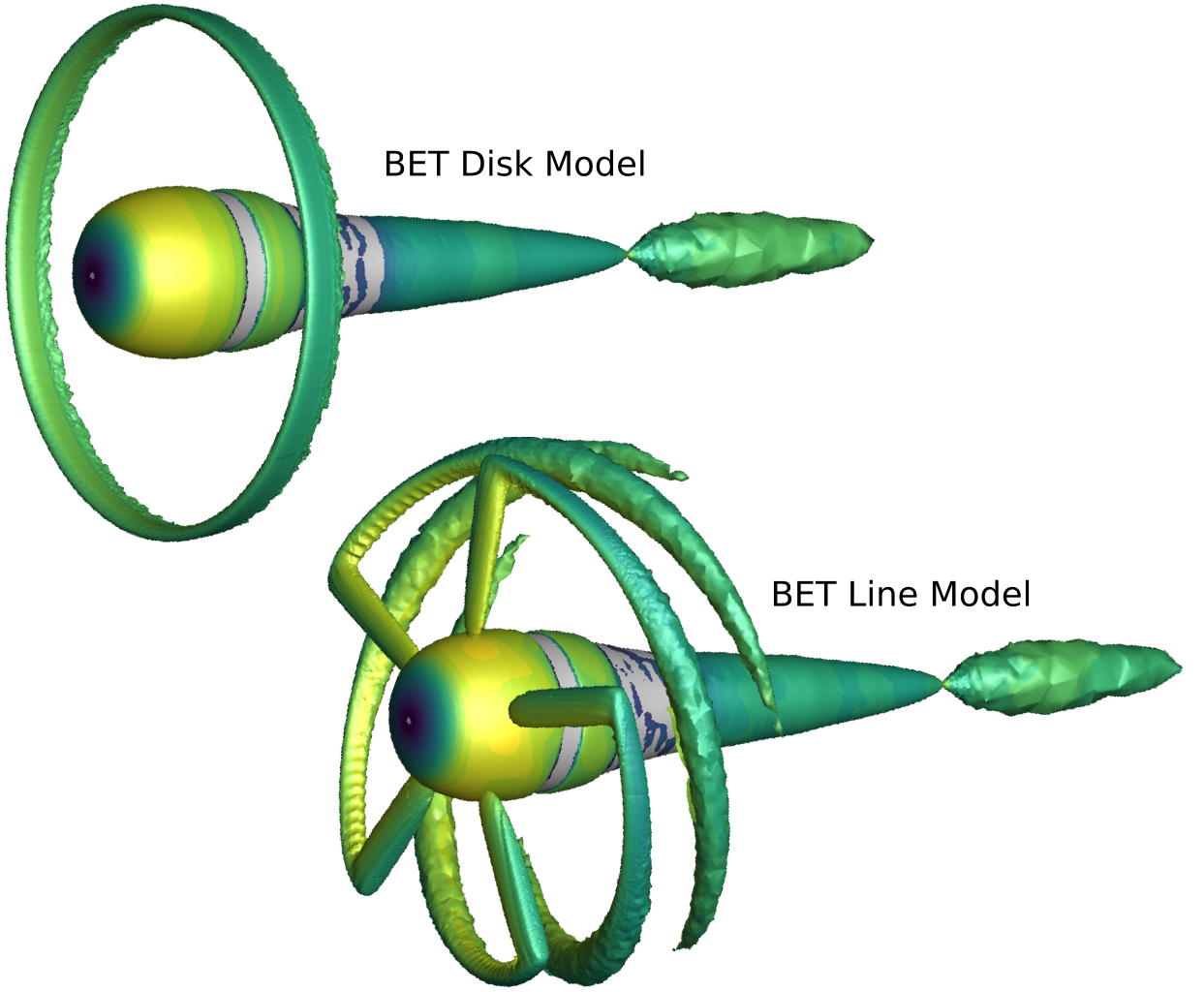
Figure 2: An example rotor simulation showcasing the characteristic flow profiles in BET Disk and BET Line models.
In summary, the order of complexity of the different models discussed is: AD < BET Disk < BET Line < body-fitted DES. Correspondingly, the order of the computational requirements for simulating these models increases in the same direction. We can expect that the BET Line model might be a good compromise, maintaining nonlinear interactions between the flow features associated with the different blades but still approximating the flow physics to lower the computational burden. In the next article, we will present the computational gains obtained thanks to the BET approach and the trade-offs involved as compared to the DES model.
This concludes Part 2 of the series. In the next and final article we will present the results we obtained when using the above described BET models for simulating the XV-15 isolated rotor. We will also compare the BET results with the DES model.
If you’d like to learn more about CFD simulations, how to optimize them, or how to reduce your simulation time from weeks or days to hours or minutes, stop by our website at Flexcompute.com or follow us on LinkedIn.
For the expanded version of the paper this content is derived from, click here.
